
How to use the Communication Test
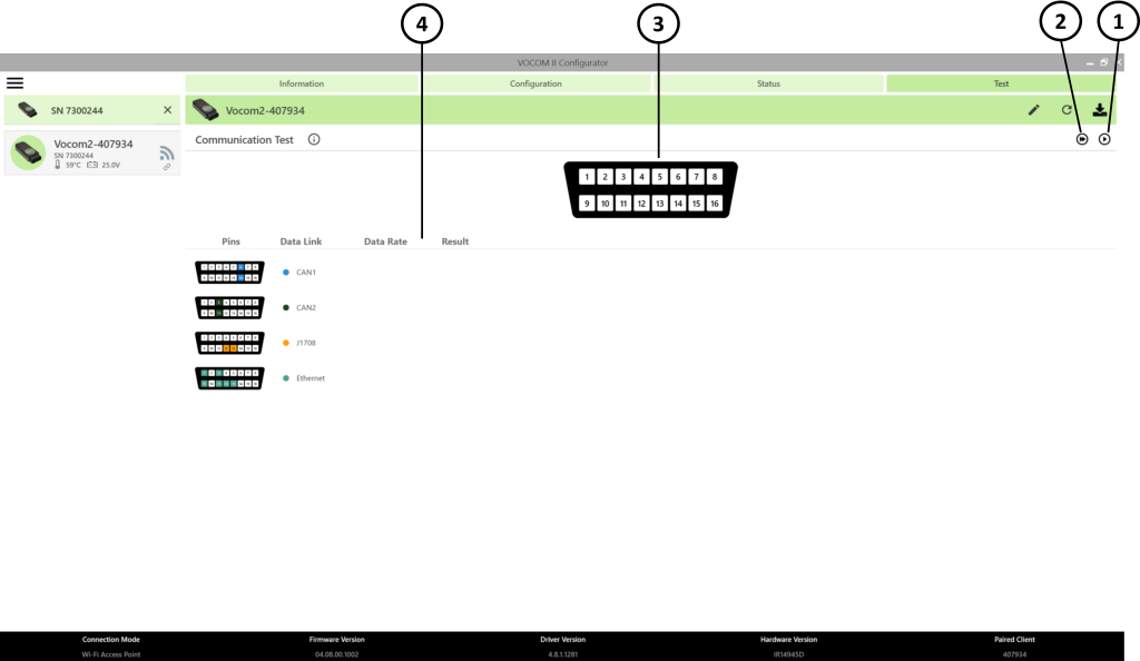
- Start communication test
- Start continuous communication test
- Detected circuit pins
- Communication test results
- The test can only be run when the paired VOCOM device is not in use by any diagnostic application. To run the test, click on the “start communication test” button. The test result will be displayed immediately after the test is complete.
- Note: You cannot use the diagnostic application when the test is running continuously.
- The VOCOM Communication Test is available in Configurator from version 4.7.0 or newer and is applicable for the VOCOM Tough and VOCOM Mini devices.
- The Communication Test is used to confirm if it is possible to communicate with the control units via the VOCOM device and the OBD cable/connector.
- The Communication Test shows the status of the data links that are found in the current connected vehicle/equipment, but the test cannot show which data links are expected to respond
- The technician needs to know what data links are expected for the connected vehicle/equipment, see Electrical architectures and data links.
Communication test results
- If the Communication Test shows that communication is not possible in any or all of the expected data link(s), it means that there is a problem with the OBD connection. The diagnostic application will either not be able to identify the vehicle/equipment, or mismatches/errors will occur.
- If the Communication Test is successful for the expected data links, it confirms that the communication is working. If there is a problem identifying the vehicle/equipment, troubleshooting must be done in the diagnostic application.
Detected circuits
In the Communication Test, the OBD connector image displays the pins as they are seen in the vehicle/equipment connector.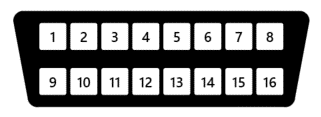
When the test is run, the detected pins will be colored.
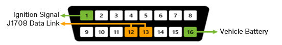
Battery voltage – Pin 16
Battery voltage must always be present (12 V or 24 V).
Ignition voltage – Pin 1
Ignition voltage must be present when J1708 is present, and its level shall be close to the battery voltage level.
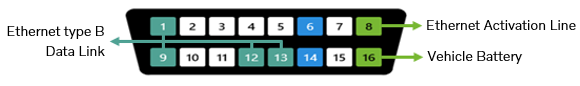
Ethernet activation line voltage – Pin 8
Ethernet activation line voltage must be present for vehicles that have Ethernet capability, and its level shall be around 75% of the battery voltage.
Electrical architectures and data links
| Data links | ||||
|---|---|---|---|---|
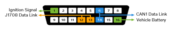
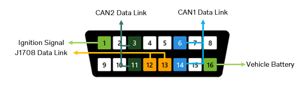
| Electrical architecture | J1708* | CAN1 | CAN2 | Ethernet** |
| VERSION2 | X | |||
| VERSION3 | X | X | ||
| VERSION3 (North America) | X | X | X | |
| VERSION4 T1 | X | |||
| VERSION4 T2 | X | X | ||
* J1708
- Pin 1 is expected to have voltage when the J1708 data link is present.
- The test can detect pin 1 voltage and J1708 traffic independently, but both are required to be present when using the diagnostic application.
** Ethernet
- The voltage level in the activation line is used to determine the Ethernet configuration.
- The difference between Ethernet types A and B is simply which pins are used:
- Ethernet type A (pins 3, 11, 12, and 13).
- Ethernet type B (pins 1, 9, 1,2, and 13).
- Volvo Group vehicles shall be detected as Ethernet type B.
Expected pins per electrical architecture
The communication test cannot say which pins are expected, but only which pins are detected.
VERSION2
VERSION3
VERSION3 (North America)
VERSION4 T1

VERSION4 T2
Communication test coverage for T2 vehicles
Note: For T2 vehicles, the communication test only validates communication with the first Ethernet node. Hence, if there are problems communicating with TGW3 and/or SEM2, then those problems relate to the internal Ethernet communication.
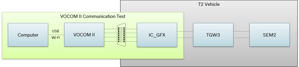
- The test does not validate communication to TGW3 and SEM2.
- If all expected pins are detected for the connected vehicle’s electrical architecture, this confirms that communication with the control units in the different data links is possible.
- When communication is detected for the expected data links, but TechTool still fails to identify the vehicle, the problem lies in TechTool. Try to restart the computer.
- When communication is not detected in an expected data link, the problem lies in the physical connection. Check the OBD cable’s pins and the terminals inside the vehicle connector.