

VOCOM Configurator
Overview
- The VOCOM Configurator application is installed automatically by installing the VOCOM driver.
- The latest available driver version can be found in downloads.
- VOCOM Configurator is installed on a Windows computer. The Configurator provides all features necessary to configure the VOCOM devices into wireless mode of operation.
Highlights of the VOCOM Configurator
- This application can be used to connect the computer to an available VOCOM device wirelessly in a very convenient way. The user could configure the VOCOM device and know the status of the connection.
- The user can perform a communication test between the VOCOM device and the vehicle only using the configurator application.
- In addition, the user can update the VOCOM device firmware, reset the device configuration, configure the auto-connect feature, and collect/read the logs.
To open the VOCOM configurator application
- Install the VOCOM configurator application on your Windows computer.
- Click the Start button on your computer and type “vocom” in the search field to find the VOCOM Configurator application.
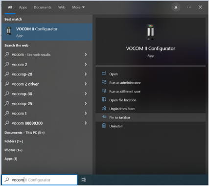
- Tip: Select “Pin to taskbar” to create a shortcut in the taskbar for easy access to the application in the future.
- Click to open the VOCOM Configurator application.
The application interface
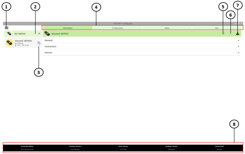
1. Menu
2. Select device/Preferred device
3. Paired icon
4. Feature bar
5. Edit device name
6. Restart device
7. Download log files from the device
8. Footer
- The three main sections of the Configurator interface are: Feature bar, Footer and Menu.
1. Feature bar
- The four main tabs within the feature bar are Information, Configuration, Status and Test.
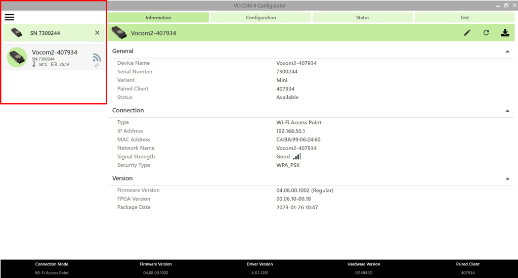
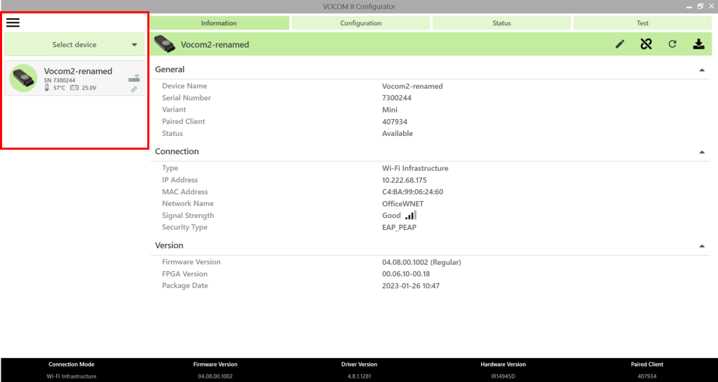
1.1 Information tab
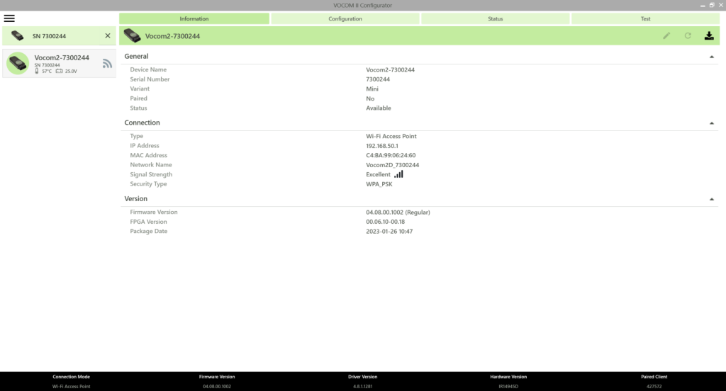
- The content in the information tab appears only after a VOCOM device is paired to a computer.
- The Information tab is the default tab when opening the application or when selecting a device from the list. The Information page displays content from the currently selected/paired device.
- This tab contains
- General information about the VOCOM device that is paired with the computer.
- Connection information (Type, IP address, MAC address, Network name, Signal strength and Security type).
- Version information (Firmware version, FPGA version, and Package date).
1.2 Configuration tab
The configuration tab offers the possibility of configuring the wireless operation mode for the paired VOCOM device, namely the access point mode, Android mode/Wi-Fi direct mode, and the infrastructure mode.
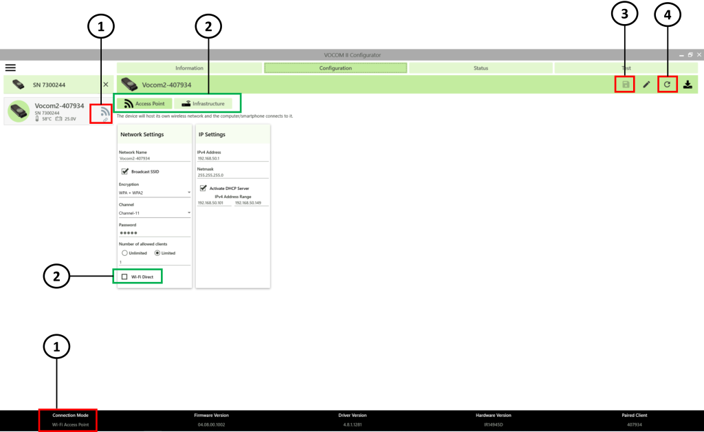
- Current connection mode
- Wireless operation modes
- Save configuration
- Restart device
- Users can choose between three wireless operation modes: the access point mode, the android mode/Wi-Fi direct mode, and the infrastructure mode to connect a VOCOM device to your computer/android device.
- Android mode/Wi-Fi direct mode of operation is found in the access point tab. By enabling this option, the VOCOM device can be connected to any Android device.
- The current connection mode in the above example is access point mode. Both the icon and the text information indicate the current mode of operation of the VOCOM device.
- If a user wishes to change the operation mode of the VOCOM device, then the user must do so by choosing the suitable operation mode, filling in the configuration information, clicking on the save configuration icon to confirm the configuration, and clicking on the restart device button to apply the configuration.
1.3 Status tab
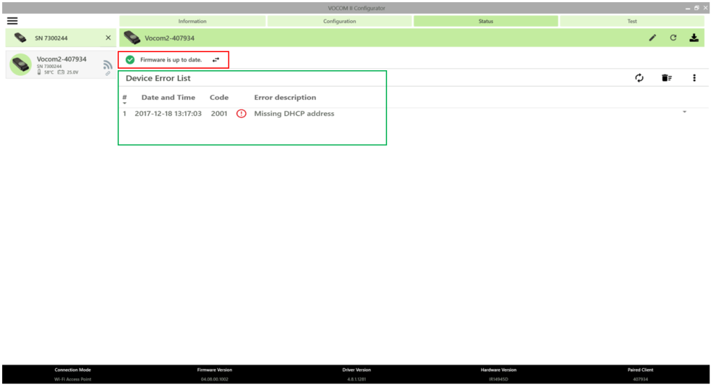
- In the status tab, you will know the firmware version of the connected VOCOM device. The configurator will automatically update the firmware of the device when connected. If the firmware is already up to date, then the message “Firmware is up to date” is displayed (highlighted in red in the above image). For more information on updating the firmware, read update driver and firmware.
- If there is any fault events occurring during usage of the VOCOM device, the respective logged error codes will be shown in this tab (highlighted in green). The contents of the internal device error list can be displayed, filtered, and cleared through the status page of the VOCOM Configurator.
1.4 Test tab
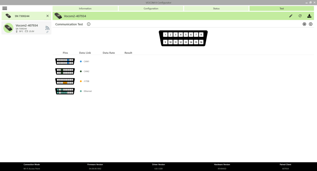
- The communication test will try to look for traffic on the different protocols. It is useful to validate that the VOCOM device can “listen” to communication data from the vehicle. Start the communication test to know the voltage reception for the different pins on the OBD connector.
- This test will only “listen” to communication data, which means that depending on the vehicle or the current condition of the vehicle nothing might be being transmitted and hence not possible to confirm if there is any communication problem or not.’
- The test will display the following information:
- IGNITION SIGNAL: Checks if there is voltage on the ignition pin.
- J1708: Checks if there is communication data on the J1708 bus.
- CAN 1: Checks if there is communication data on channel 1 of the CAN bus.
- CAN 2: Checks if there is communication data on channel 2 of the CAN bus.
- Read more about the communication test here.
2. Footer

- The footer in the bottom of the application interface shows the following information:
- Connection mode
- Firmware version
- Driver version
- Hardware version
- Paired client
3. Menu
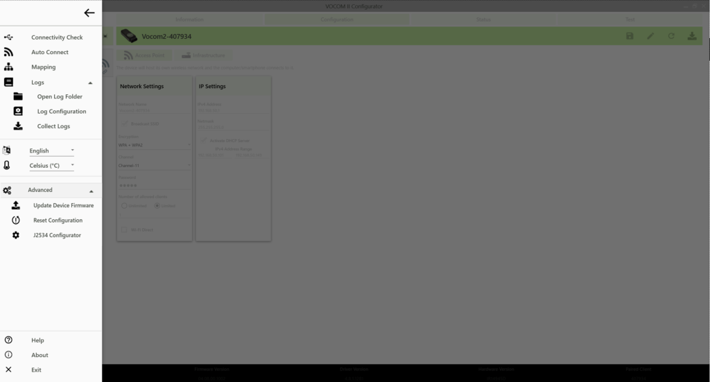
- The Menu contains:
3.1 Connectivity Check
- If there are issues when a VOCOM device is connected via USB but is not being detected, use the connectivity check to identify potential issues.
- The connectivity check will identify and try to communicate with a USB-connected VOCOM device, and then display the results.
- For detailed instructions about connectivity check, read connectivity check.
- For a breakdown of what the results mean check the chapter Troubleshooting-USB connection.
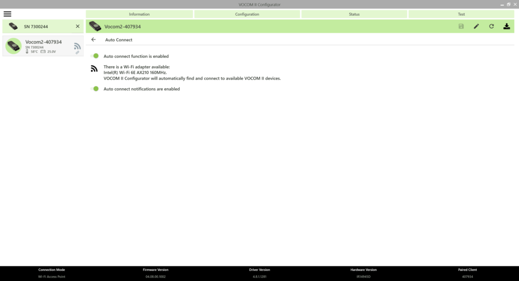
3.2 Auto Connect
- Auto connect allows the user to toggle (enable/disable) between the “auto connect function” and the “Auto connect notifications”.
3.3 Mapping
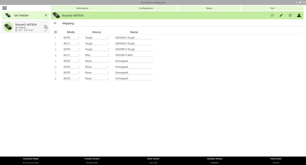
- Normally the mapping does not need to be changed. This feature is to be used only in very specific cases for experienced users.
- A wrong mapping will cause the diagnostic application to not connect to the VOCOM device.
For more information, read Mapping.
3.4 Log Configuration
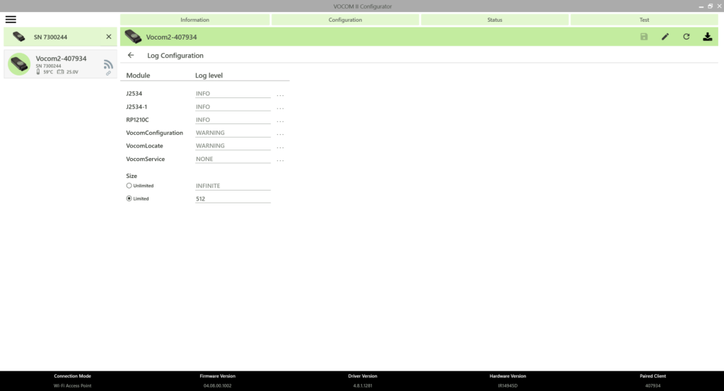
- Log levels can be changed per log module.
- The available VOCOM log modules are as follows:
| Logging module | Description | Scope |
| J2534 | Diagnostic communication logs | Windows logs and device logs |
| J2534-1 | Diagnostic communication logs | Windows logs and device logs |
| RP1210C | Diagnostic communication logs | Windows logs and device logs |
| VocomConfiguration | Configuration API logs | Windows logs |
| VocomLocate | Locate API logs | Windows logs |
| VocomService | Service logging | Windows logs |
- To change the log level of a particular module, perform the following steps:
- Open the Log Configuration page by clicking the Logs dropdown in the Menu.
- Change the Log level of one or more log Modules by clicking on the three dots shown next to each module.
- Click Save.
- Note: Log level changes will immediately take effect after step 3, no reboot is necessary.
- Changing the log level for components with the scope “Windows logs and device traces” will affect both the log level on the device side and on the computer side. This is the case for the VOCOM diagnostic APIs, i.e. RP1210C API and J2534/J2534-1 API.
- VOCOM Windows logs can be found under “C:\ProgramData\ACTIA I+ME GmbH\VOCOM II\Log”.
- Note: Log levels will be reset to their default values by an installer update.
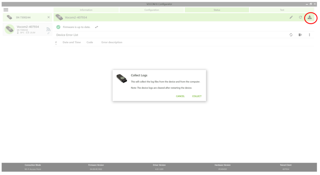
3.5 Collect Logs
- The Device Logs are typically needed for debugging purposes and support cases, normally the help desk may request this data from you.
- Select Collect Logs > Click on “Collect”.
- Alternatively, click on the “Download log files from the device ” button highlighted in red in the below image.
- The logs will be downloaded and saved on a default location.
- The log folder will automatically open with the latest log files selected.
3.6 Change Language
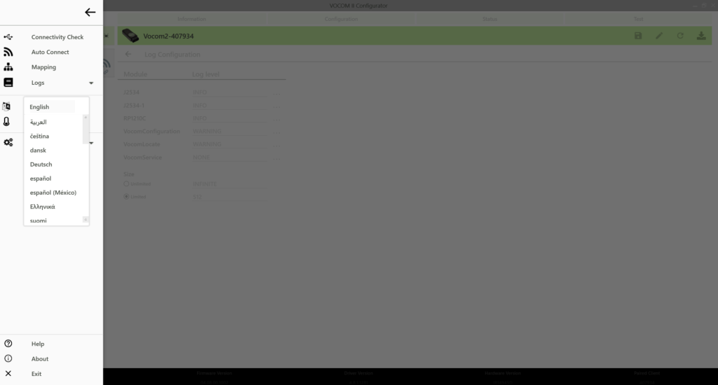
- The VOCOM Configurator supports multiple languages. English is the default display language.
- To change the display language, perform the following steps:
- Open the Options Menu
- Select your language from the drop-down.
- Restart the VOCOM Configurator.
- This setting will automatically apply to the VOCOM Monitor and its notifications.
3.7 Change Temperature Unit
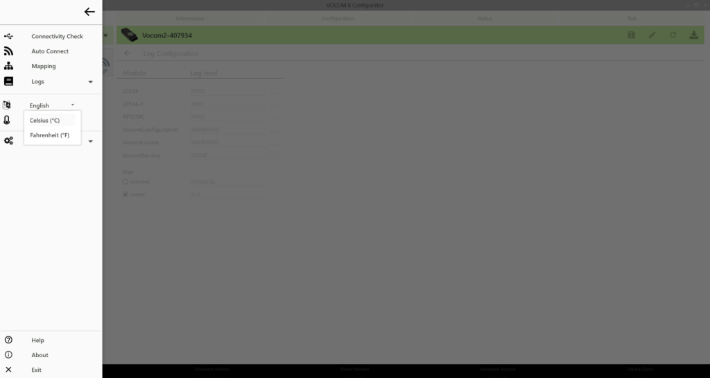
- This will change the temperature unit of the temperature value displayed for each device in the device list.
- To change the unit system, perform the following steps:
- Open the Options Menu
- Select the desired temperature unit (Celsius or Fahrenheit) from the drop-down.
- No need to restart the Configurator.
3.8 Update Device Firmware
- Updating the device firmware is performed automatically.
- However, if the user intends to manually update the device firmware, then it is possible as well. For more information on this, read update firmware manually.
3.9 Reset Configuration
A reset will revert the device configuration to its default state:
- Default device name (Vocom2-xxxxxx)
- Default Wi-Fi configuration (Wi-Fi Access Point)
- Default pairing (not paired)
For more information, read reset configuration.
3.10 J2534 Configurator
- Using this option, a user can configure the VOCOM device for J2534 usage.
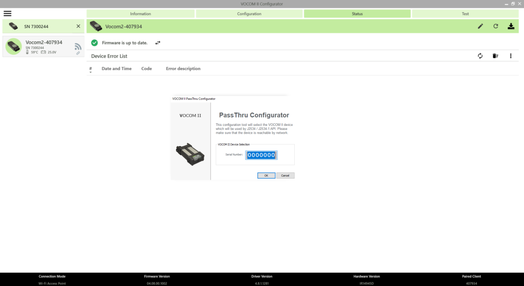
- To select the active J2534/J2534-1 PassThru device, perform the following steps:
- Go to the VOCOM PassThru Configurator tool found under the Options menu in the VOCOM Configurator application.
- In the PassThru Configurator dialog, enter the serial number of the VOCOM device that will be used as the PassThru device on the client PC.
- Click OK.
- Check the box : The active J2534/J2534-1 PassThru device is selected.
- The VOCOM serial number is a 7-digit string of the form “7xxxxxx”.
- The VOCOM PassThru device settings are reset by an installer update.
3.11 About
- Clicking the About item displays version information about the VOCOM Configurator application.
3.12 Help
- Clicking the Help item will open and display the VOCOM Tough Operation Instructions.
3.13 Exit
- Clicking Exit will close the Configurator application.
Visibility of VOCOM devices in the configurator application
Visibility in access point mode
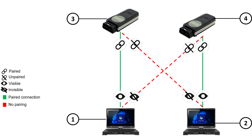
- Computer-1
- Computer-2
- VOCOM-1
- VOCOM-2
- When a VOCOM device is paired with a computer in access point mode, that particular VOCOM device will be visible to only that computer and no other computer will be able to see the VOCOM device.
- In the above example, Computer-1 is paired with VOCOM-1 and therefore can only see VOCOM-1. So, VOCOM-2 is not visible to Computer-1.
- Similarly, since Computer-2 is paired with VOCOM-2, VOCOM-1 is not visible to Computer-2 in the configurator application. Therefore, there is no “Select Device” dropdown shown to select any other VOCOM device nor there is any unpair button shown. So, the user has to remove the current preferred device by clicking on ‘x’ to pair a different VOCOM device in access point mode.
Visibility in Infrastructure Mode
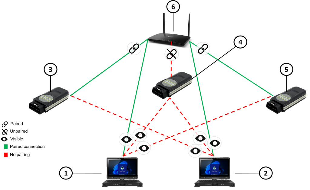
- Computer-1
- Computer-2
- VOCOM-1
- VOCOM-2
- VOCOM-3
- Infrastructure access point
- When a VOCOM device is connected to a computer via infrastructure mode, the VOCOM device can be paired to only one computer as usual but will still be visible to any computer that is connected to the same access point.
- In the above example, Computer-1 is paired with VOCOM-1 but VOCOM-2 and VOCOM-3 are both also visible to Computer-1 in the configurator application. This is because Computer-1 and all three VOCOM devices are connected to the same access point.
- Similarly, Computer-2 is paired with VOCOM-3 but VOCOM-1 and VOCOM-2 are both also visible to Computer-1 in the configurator application. There is a “Select Device” dropdown shown where all the other VOCOM devices connected to the same network are shown. Users can click on the unpair button and select a different VOCOM device from the list in order to pair with it.
- VOCOM-2 is not paired with either of the computers but is still visible to both computers since they are all in the same network.