

VOCOM II Tough
Hardware
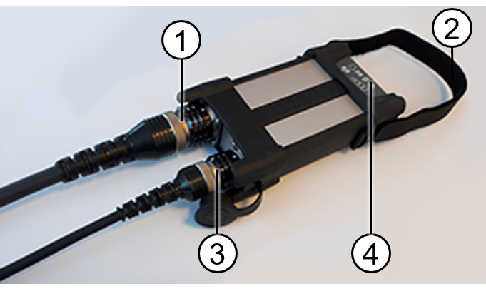
- ECTA-26/OBD connector
- Carry strap with velcro fastener
- ECTA-12/USB connector with dust cap
- Plastic cap with function indicators
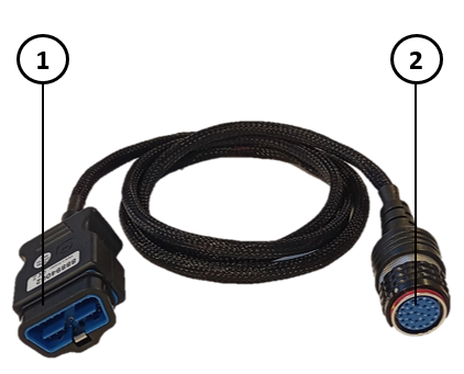
- OBD connector
- ECTA-26 connector
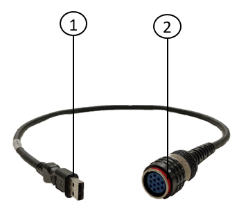
- USB connector
- ECTA-12 connector
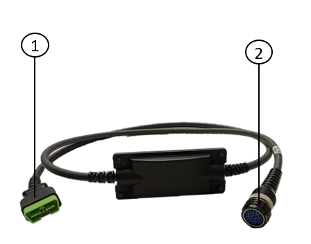
- OBD connector
- ECTA-26 connector
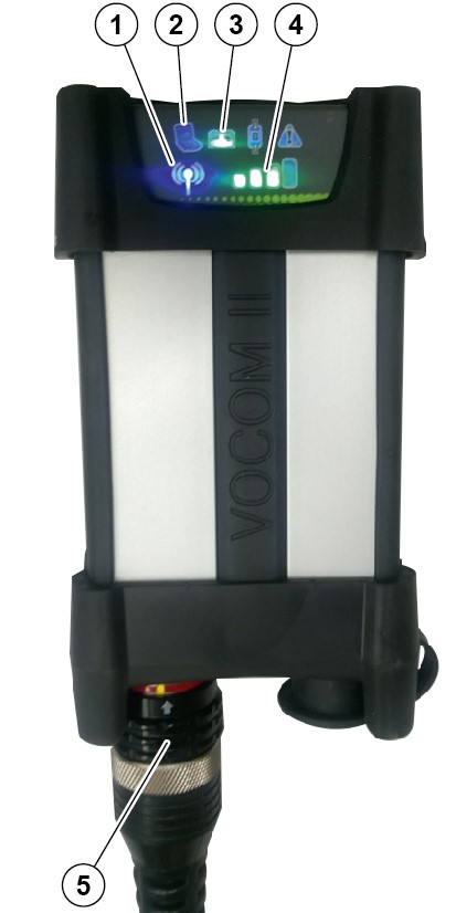
Indicators
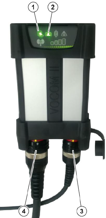
- Computer-USB connection
- Vehicle/Equipment battery
- ECTA/USB connector
- ECTA/OBD connector
- Wireless connection
- Computer-USB connection
- Vehicle/Equipment battery
- Wireless signal
- ECTA/OBD connector
Function Indicators
- The device has six function indicators with different colors to indicate the operating statuses and dangers of VOCOM II Tough.
- The table below describes the function indicators’ symbols, names, and what the colors and behaviors of the different LEDs mean:
| Symbol | Indicator name | Description |
|---|---|---|
 | Vehicle/Equipment battery | Multi-color LED · Green: Normal voltage level · Orange: Too low voltage · Red: Critically low voltage |
 | Computer-USB connection | Multi-color LED · Continuous green: USB powered · Flashing green: Computer communication activity · Continuous orange: Booting · Flashing orange: Firmware update |
 | Warning | Multi-color LED · Continuous orange: Warning · Continuous red: Critical error · Flashing orange: Overtemperature |
 | Wireless connection | Blue LED · Flashing slowly while no wireless signal bars are lit: Looking for a connection · Continuous: Connected · Flashing fast: Wireless communication |
 | Wireless signal | · Red bar: Wireless connectivity problem · Green bars: Signal quality |
 | Smartcable connectivity | Green LED · Continuous: Smartcable connected |
Vehicle/Equipment battery
- If the VOCOM II Tough is connected to a vehicle/equipment, the battery icon will display the voltage level of the connected vehicle/equipment’s battery.
- Note: VOCOM II Tough has no internal battery.
| Vehicle/Equipment battery indicator color | Battery condition | 12 V Battery | 24 V Battery |
|---|---|---|---|
| Green | Battery level normal | > 12.15 V | > 24.3 V |
| Orange | Battery level low | 11.6 V – 12.15 V | 23.2 V – 24.3 V |
| Red | Battery level critically low | < 11.6 V | < 23.2 V |
Computer-USB connection
- After connecting VOCOM II Tough via USB, when the Computer-USB connection status LED is lit green, it means the VOCOM II Tough is ready to communicate with the computer.
Warning icon
- The warning icon is lit orange when the temperature of the device is very high. In such an event, stop using the device until the ambient temperature is low enough. The optimum operating temperature is -40°C to +85°C.
- The warning icon is lit red during the critical events and errors occurring in the device and this is also logged in an internal device error list. Clearing the device error list using VOCOM II configurator will reset the state of the warning LEDs.
Wireless connection icon
- When using VOCOM II Tough in the wireless operation mode, the wireless connection icon will be lit blue confirming that the VOCOM II Tough has been connected to a client network successfully.
Wireless Signal icon
- Depending on the mode of operation, the wireless signal icon shows the signal strength of the related connection.
- In access point mode, the wireless signal icon shows the signal strength between the VOCOM II device and the USB adapter that is attached to the computer. Make sure to place your computer closest possible to the VOCOM II device (all four signal bars will be lit green in this case) ensuring an uninterrupted connection.
- In infrastructure mode, the wireless signal icon shows the signal strength between the VOCOM II device and the Wi-Fi router. Since the Wi-Fi router itself is mounted in a fixed location, the truck and the VOCOM II device both need to be close to the router to ensure an uninterrupted connection.
Smartcable icon
- This icon is lit green only when the smartcable is connected to the diagnostic connector in the truck. The smartcable is compatible with only legacy Renault trucks.
Reset Button
- The reset button for factory reset is integrated into the front protector.
- To perform a factory reset, follow reset configuration.
- Resetting the VOCOM II device to factory defaults will reset the following:
- Device name
- Paired client
- Wireless configuration
Note: Resetting the device does not revert the firmware version.
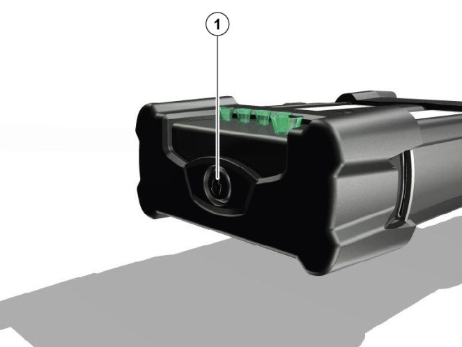
- Reset button
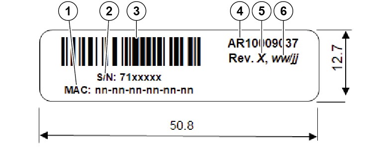
Identification Label
The identification label is attached to the VOCOM II Tough housing. The following information is presented:
- AR1000903X: Article number, 10009037 for VOCOM II Tough and 10009039 for VOCOM II Dongle/Mini.
- Rev. X: Hardware revision, revision D being the initial production revision.
- ww/jj: Production date, week/year.
- S/N 7xxxxxx: Serial number, starting with 7100001 for VOCOM II Tough and 7300001 for VOCOM II Dongle/Mini.
- Bar code: S/N as C128 bar code.
- MAC: nn-nn-nn-nn-nn-nn: MAC address of wireless interface.
- MAC address
- Serial number
- C128 bar code
- Article number
- Hardware revision
- Production date